Aviation Maintenance Technician > SOLUTIONS MANUAL > Aircraft Structures for Engineering Students 7th Edition T. H. G Megson | Solutions Manual (All)
Aircraft Structures for Engineering Students 7th Edition T. H. G Megson | Solutions Manual
Document Content and Description Below
Last updated: 1 year ago
Preview 5 out of 390 pages
Instant download

Loading document previews ...
Buy this Document to get the Full Access Instantly
Provided by Students Who Aced it
We Verify Document Content to Gurantee Accuracy
Reviews( 0 )
Document information
Connected school, study & course
About the document
Uploaded On
Apr 05, 2025
Number of pages
390
Written in
All

Additional information
This document has been written for:
Uploaded
Apr 05, 2025
Downloads
0
Views
88
Document Keyword Tags
Recommended For You
Get more on SOLUTIONS MANUAL »
Aircraft Structures for Engineering Students 7th Edition T. H....

Solutions Manual for Aircraft Structures for Engineering Stude...
Solution Manual for Aircraft Structures for Engineering Studen...

Solution Manual For Aircraft Structures for Engineering Studen...
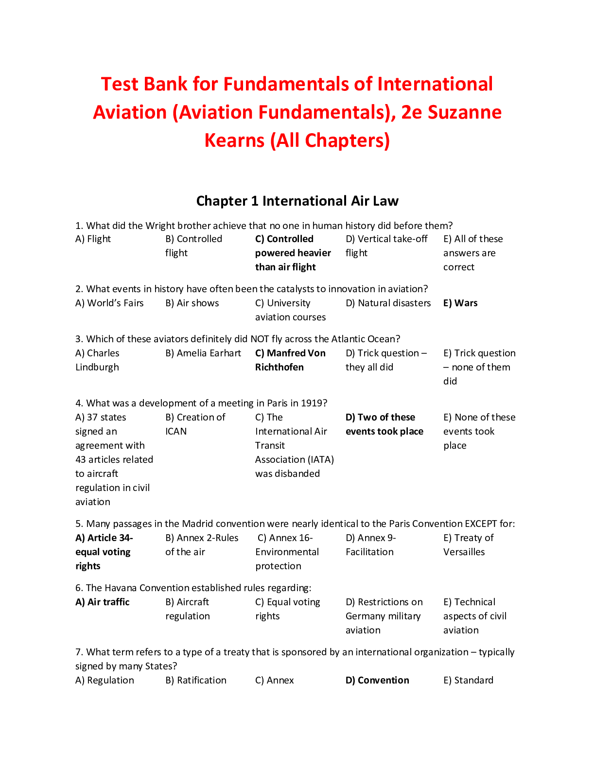
Fundamentals of International Aviation (Aviation Fundamentals)...

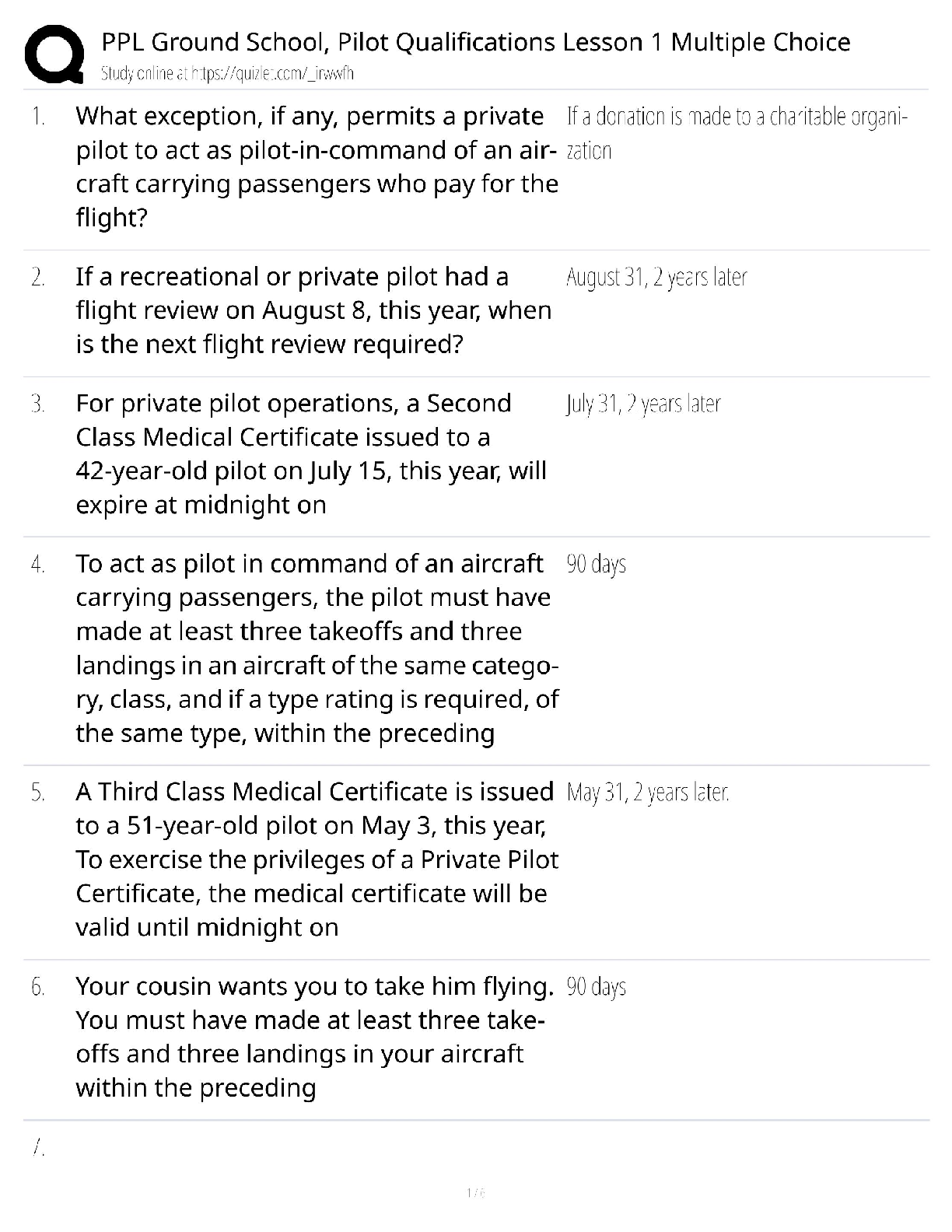
PPL Ground School / Pilot Qualifications Lesson 1 / Multiple C...
AVIA 300 King Schools FIRC Study / Flight Instructor Refresher...
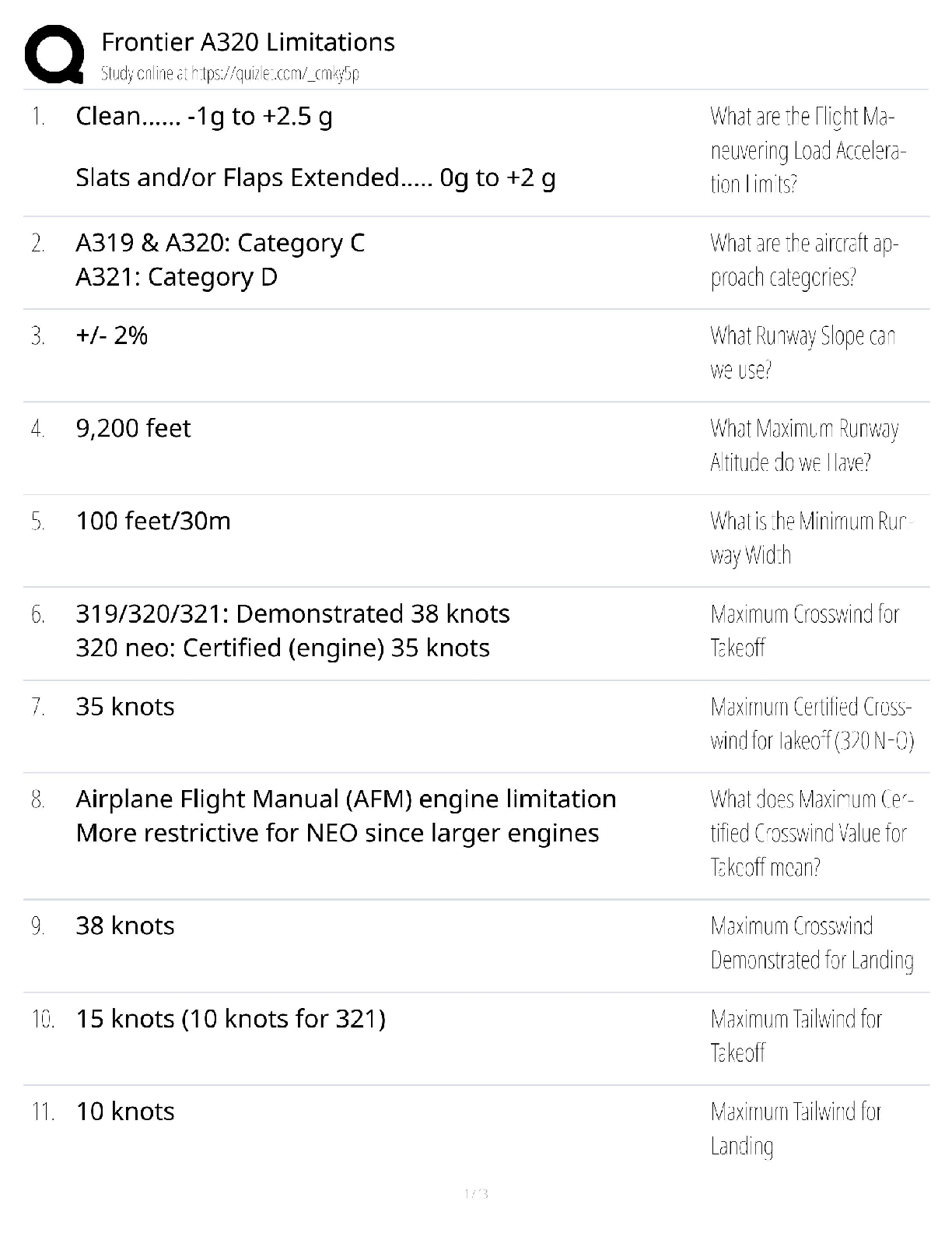
AVIA 420 Frontier A320 Limitations / Aircraft Systems Study Gu...
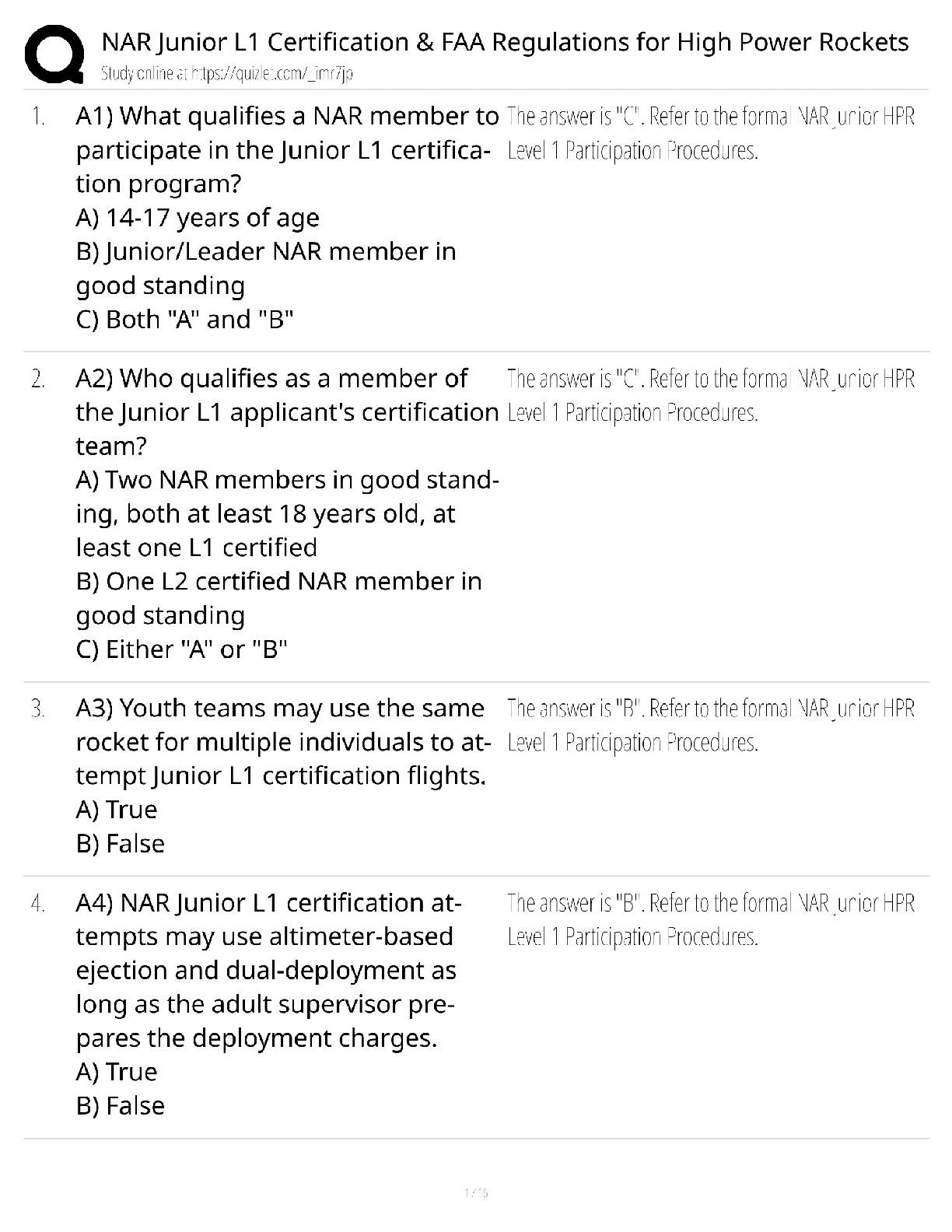
NAR Junior L1 High Power Rocketry Certification / FAA Regulati...
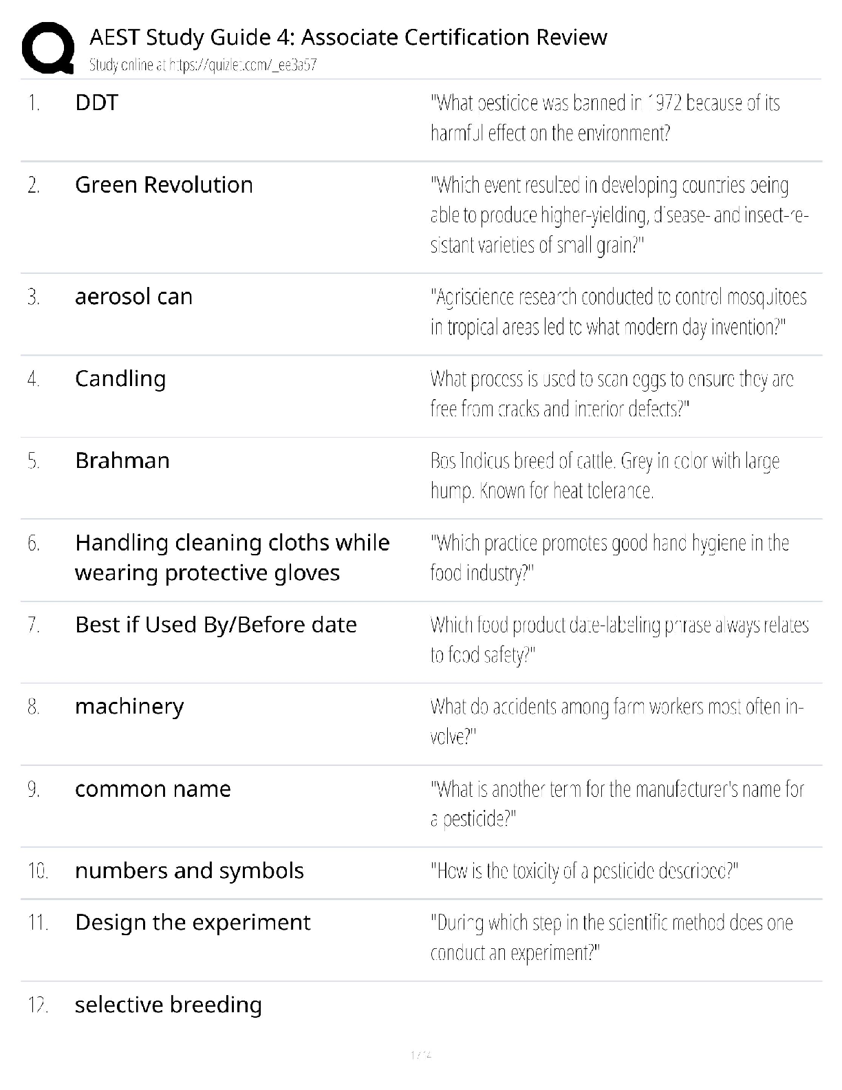
AEST Associate Certification / Study Guide 4 & Exam Review / 2...