Physics > Lab Report > LAB Report for Experiment RC Circuits ( well written report ) 2017 (All)
LAB Report for Experiment RC Circuits ( well written report ) 2017
Document Content and Description Below
Last updated: 4 months ago
Preview 1 out of 14 pages
Instant download
.png)
Buy this Document to get the Full Access Instantly
Provided by Students Who Aced it
We Verify Document Content to Gurantee Accuracy
Reviews( 0 )
Document information
Connected school, study & course
About the document
Uploaded On
Jun 15, 2021
Number of pages
14
Written in
All

Additional information
This document has been written for:
Uploaded
Jun 15, 2021
Downloads
0
Views
139
Document Keyword Tags
Recommended For You
Get more on Lab Report »
Northeastern UniversityPHYS 1152Report for Experiment 18 R-C C...

.png)


Northeastern UniversityPHYS 1152Experiment 18 RC Circuits ( wr...
.png)
Northeastern University PHYS 1155 Experiment18 RC CIRCUITS ( 2...


Laboratory Techniques Lab Report Option One: Density Measureme...
Florida Atlantic University - PHY 2048LPhysics Lab Report Expe...


Plasma Physics, 2e by Richard Fitzpatrick (Solutions Manual)


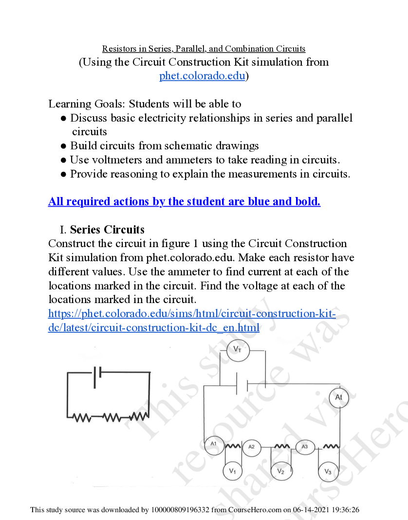
Resistors in Series, Parallel, and Combination Circuits PHET L...