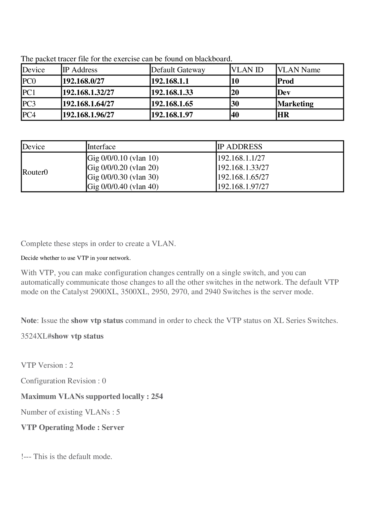
The packet tracer file for the exercise can be found on blackboard.
Device IP Address Default Gateway VLAN ID VLAN Name
PC0 192.168.0/27 192.168.1.1 10 Prod
PC1 192.168.1.32/27 192.168.1.33 20 Dev
PC3 192.168.1.64/2
...
The packet tracer file for the exercise can be found on blackboard.
Device IP Address Default Gateway VLAN ID VLAN Name
PC0 192.168.0/27 192.168.1.1 10 Prod
PC1 192.168.1.32/27 192.168.1.33 20 Dev
PC3 192.168.1.64/27 192.168.1.65 30 Marketing
PC4 192.168.1.96/27 192.168.1.97 40 HR
Device Interface IP ADDRESS
Router0 Gig 0/0/0.10 (vlan 10)
Gig 0/0/0.20 (vlan 20)
Gig 0/0/0.30 (vlan 30)
Gig 0/0/0.40 (vlan 40) 192.168.1.1/27
192.168.1.33/27
192.168.1.65/27
192.168.1.97/27
Complete these steps in order to create a VLAN.
1. Decide whether to use VTP in your network.
With VTP, you can make configuration changes centrally on a single switch, and you can automatically communicate those changes to all the other switches in the network. The default VTP mode on the Catalyst 2900XL, 3500XL, 2950, 2970, and 2940 Switches is the server mode.
Note: Issue the show vtp status command in order to check the VTP status on XL Series Switches.
3524XL#show vtp status
VTP Version : 2
Configuration Revision : 0
Maximum VLANs supported locally : 254
Number of existing VLANs : 5
VTP Operating Mode : Server
!--- This is the default mode.
VTP Domain Name :
VTP Pruning Mode : Disabled
VTP V2 Mode : Disabled
VTP Traps Generation : Disabled
MD5 digest : 0xBF 0x86 0x94 0x45 0xFC 0xDF 0xB5 0x70
Configuration last modified by 0.0.0.0 at 0-0-00 00:00:00
2. After you set and verify the VTP domain, begin to create VLANs on the switch.
By default, there is only a single VLAN for all ports. This VLAN is called default . You cannot rename or delete VLAN 1.
Issue the show vlan command in order to check the VLAN information.
3524XL#show vlan
VLAN Name Status Ports
---- -------------------------------- --------- -------------------------------
1 default active Fa0/1, Fa0/2, Fa0/3, Fa0/4,
Fa0/5, Fa0/6, Fa0/7, Fa0/8,
Fa0/9, Fa0/10, Fa0/11, Fa0/12,
Fa0/13, Fa0/14, Fa0/15, Fa0/16,
Fa0/17, Fa0/18, Fa0/19, Fa0/20,
Fa0/21, Fa0/22, Fa0/23, Fa0/24,
Gi0/1, Gi0/2
1002 fddi-default active
1003 token-ring-default active
1004 fddinet-default active
1005 trnet-default active
VLAN Type SAID MTU Parent RingNo BridgeNo Stp BrdgMode Trans1 Trans2
---- ----- ---------- ----- ------ ------ -------- ---- -------- ------ ------
1 enet 100001 1500 - - - - - 1002 1003
1002 fddi 101002 1500 - - - - - 1 1003
1003 tr 101003 1500 1005 0 - - srb 1 1002
1004 fdnet 101004 1500 - - 1 IBM - 0 0
1005 trnet 101005 1500 - - 1 IBM - 0 0
Issue this set of commands in privileged mode in order to create another VLAN:
3524XL#vlan database
!--- You must enter into VLAN database in order to configure any VLAN.
3524XL(vlan)#vtp server
Device mode already VTP SERVER.
!--- You can skip this command if the switch is already in server mode and you
!--- want the switch to be in server mode.
Note: A switch can only create VLANs if it is in VTP server mode or VTP transparent mode. Refer to Understanding VLAN Trunk Protocol (VTP) for more information on VTP.
524XL(vlan)#vlan ?
<1-1005> ISL VLAN index
3524XL(vlan)#vlan 2 ?
are Maximum number of All Route Explorer hops for this VLAN
backupcrf Backup CRF mode of the VLAN
bridge Bridging characteristics of the VLAN
media Media type of the VLAN
mtu VLAN Maximum Transmission Unit
name Ascii name of the VLAN
parent ID number of the Parent VLAN of FDDI or Token Ring type VLANs
ring Ring number of FDDI or Token Ring type VLANs
said IEEE 802.10 SAID
state Operational state of the VLAN
ste Maximum number of Spanning Tree Explorer hops for this VLAN
stp Spanning tree characteristics of the VLAN
tb-vlan1 ID number of the first translational VLAN for this VLAN (or zero
if none)
tb-vlan2 ID number of the second translational VLAN for this VLAN (or zero
if none)
[Show More]